
NDT
Non Destructive Testing (NDT) – Process, Types & Applications Explained
nsure the integrity, safety, and reliability of your equipment with advanced Non-Destructive Testing solutions. We provide accurate inspection services that detect defects without causing damage, helping maximize asset performance and operational safety.
Introduction of Non-Destructive Test
ENCE710 – Advanced Steel Structures
C. C. Fu, Ph.D., P.E.
Department of Civil & Environmental Engineering
University of Maryland
College Park, MD
Definition of NDT
The use of noninvasive techniques to determine the integrity of a material, component or structure or quantitatively measure some characteristic of an object. i.e. Inspect or measure without doing harm.
What are Some Uses of NDE Methods?
- Flaw Detection and Evaluation
- Leak Detection
- Location Determination
- Stress (Strain) and Dynamic Response Measurements
- Dimensional Measurements
- Structure and Microstructure Characterization
- Estimation of Mechanical and Physical Properties
- Fluorescent penetrant indication
- Material Sorting and Chemical Composition Determination
When are NDE Methods Used?
- To assist in product development
- To screen or sort incoming materials
- To verify proper processing such as heat treating
- To verify proper assembly
- To inspect for in-service damage
- To monitor, improve or control manufacturing processes
There are NDE application at almost any stage in the production or life cycle of a component.
Nondestructive Testing
- Advantages
- Can test in-service structures
- Evaluate surface and internal conditions
- Cost efficient
- Disadvantages
- Reliability (measurements are made indirectly)
- Qualitative
- Requires a skilled professional for interpretation of results
Destructive Testing
- Advantages
- Reliable (direct measurements)
- Quantitative
- Directly relates to material properties
- Disadvantages
- Cannot test in-service structures
- Requires a model
- Costly & Time Consuming
- Multiple tests are sometimes required
Six Most Common NDT Methods
- Visual
- Liquid Penetrant
- Magnetic
- Ultrasonic
- Eddy Current
- X-ray
Visual Inspection
Most basic and common inspection method.
- Tools include:
- Fiberscopes
- Borescopes
- Magnifying glasses
- Mirrors
Portable video inspection unit with zoom allows inspection of large tanks and vessels, railroad tank cars, sewer lines.
Robotic crawlers permit observation in hazardous or tight areas, such as air ducts, reactors, pipelines.
Liquid Penetrant Inspection
A liquid with high surface wetting characteristics is applied to the surface of the part and allowed time to seep into surface breaking defects.
A developer (powder) is applied to pull the trapped penetrant out the defect and spread it on the surface where it can be seen.
Visual inspection is the final step in the process. The penetrant used is often loaded with a fluorescent dye and the inspection is done under UV light to increase test sensitivity.
The excess liquid is removed from the surface of the part.
Liquid Penetration Process
- Clean surface
- Apply liquid penetrant
- Remove excess penetrant
- Apply developer
- Inspect
- Post-cleaning
DYE PENETRANTS
These are an aid to visual inspection.
- Use correct type.
- Will only find surface defects
- Types
- Flouresant
- Red
- CAUTION
- Oil based
- Water washable
Dye Penetrant Test
Dye penetrant testing locates minute surface cracks and porosity.
- Dye types that may be used include:
- Color contrast dye – which shows up under ordinary light
- Fluorescent dye – which shows up under black light
The dye is normally applied by spraying it directly on the weld.
(AISC & NISD 2000)
Magnetic Particle Inspection
The part is magnetized. Finely milled iron particles coated with a dye pigment are then applied to the specimen.
These particles are attracted to magnetic flux leakage fields and will cluster to form an indication directly over the discontinuity.
This indication can be visually detected under proper lighting conditions.
- Magnetic Particle Process
- Magnetize surface
- Discontinuities create a magnetic flux
- Sprinkle magnetic particles
- Inspect
Magnetic Particle Crack Indications
- MAGNETIC PARTICLE
- Mainly for surface defects
- Some sub surface defects can be found
- Only ferrous metal
Magnetic Particle Inspection
Magnetic particle inspection uses powdered magnetic particles to indicate defects in magnetic materials.
- A magnetic field is induced in the part.
- The magnetic powder is attracted to and outlines cracks within the material.
- (AISC & NISD 2000)
Ultrasonic Imaging
High resolution images can be produced by plotting signal strength or time-of-flight using a computer-controlled scanning system.
- Gray scale image produced using the sound reflected from the back surface of the coin (inspected from "heads" side).
- Gray scale image produced using the sound reflected from the front surface of the coin.
Ultrasonic Testing
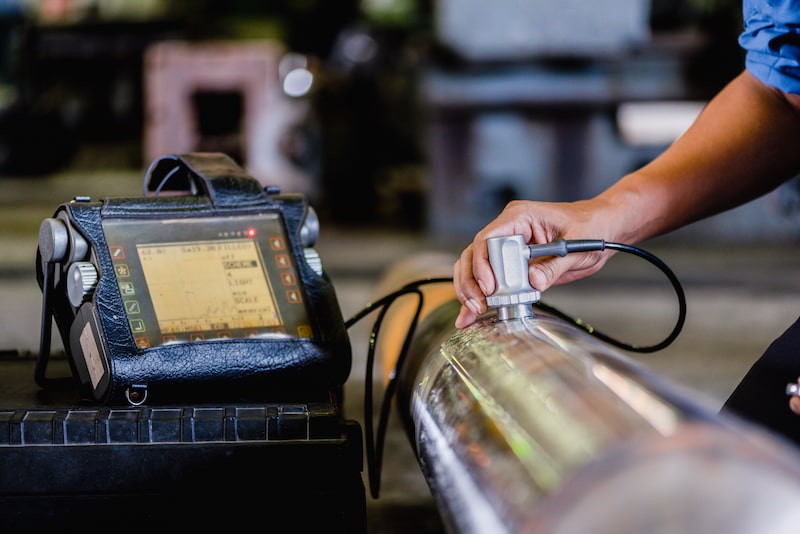
This uses high pitched sound.
The sound will not pass through an air gap so bounces back and is picked up on a receiver.
The reader is an oscilloscope.
ULTRA SONIC Device
- Ultrasonic Inspection
- Ultrasonic inspection can be used to detect flaws inside welds.
- High frequency sound waves are directed into the metal with a probe held at a specific angle.
- The flaws reflect some energy back to the probe.
- Flaws show up as indications on a screen and are subject to interpretation by an inspector.
- (AISC & NISD 2000)
- Ultrasonic
- Usage: Inspection of Raw Products
- Forgings
- Castings
- Extrusions
- etc
- Usage: Inspection Following Secondary Processing
- Machining
- Welding
- Grinding
- Heat treating
- Plating
- etc
- Usage: Inspection For In-Service Damage
- Cracking
- Corrosion
- Erosion/Wear
- Heat Damage
- etc
- Probe signals produced by various amounts of corrosion thinning.
- Usage: Power Plant Inspection
- Periodically, power plants are shutdown for inspection.
- Inspectors feed eddy current probes into heat exchanger tubes to check for corrosion damage.
- Usage: Storage Tank Inspection
- Robotic crawlers use ultrasound to inspect the walls of large above ground tanks for signs of thinning due to corrosion.
- Cameras on long articulating arms are used to inspect underground storage tanks for damage.
- Usage: Pressure Vessel Inspection
- To protect against this dangerous event, the tanks are inspected using radiography and ultrasonic testing.
- The failure of a pressure vessel can result in the rapid release of a large amount of energy.
Pipeline Inspection
NDT is used to inspect pipelines to prevent leaks that could damage the environment.
- Visual inspection, radiography and electromagnetic testing are some of the NDT methods used.
- Remote visual inspection using a robotic crawler.
- Magnetic flux leakage inspection.
- This device, known as a pig, is placed in the pipeline and collects data on the condition of the pipe as it is pushed along by whatever is being transported.
- Radiography of weld joints.
Our Client


EMI Electro Magnetic inspection
2 7/8” To 7 5/8” Drill Pipe and Tubing
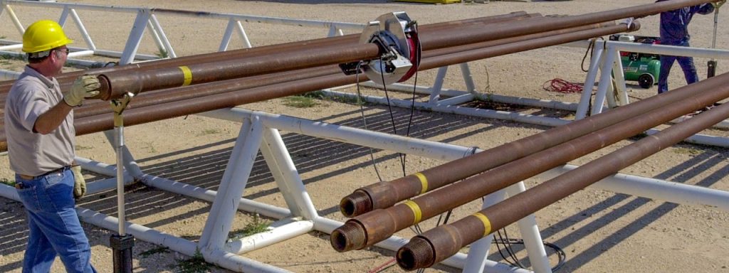
Mode of Operation
The VEDAQ-PRO™ system is calibrated on a reference standard before beginning inspection. To start, the magnetizing coil is positioned over the end of the drill pipe. The buggy drive and sensor head are then placed on top of the pipe, with the magnetizing coil mounted onto the buggy assembly.
Once the equipment is in position, pneumatic jacks lift the pipe to ensure the buggy and coil can travel freely above the pipe racks. The electronics operator initiates the inspection by powering the buggy and launching the software. While the buggy traverses the length of the pipe, the operator monitors live data through the system interface.
Upon reaching the opposite end, the jacks lower the pipe back onto the racks. The buggy and coil are then removed and repositioned on the next pipe for inspection in the reverse direction. This process is repeated for each pipe in the batch.